FREE 1 to 3-Day Delivery on Orders $119+ Details
Best Sellers


How to Install ReadyLIFT 4 in. SST Lift Kit (09-18 4WD RAM 1500 w/o Air Ride) on your Dodge RAM
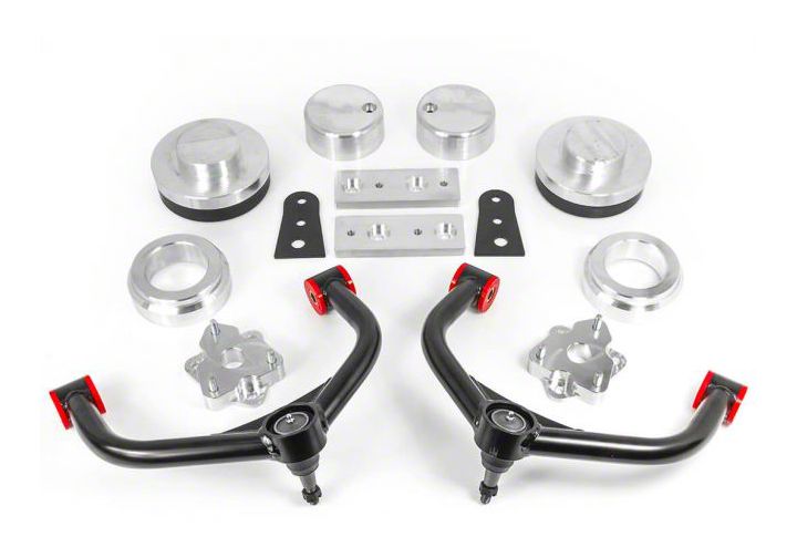
Shop Parts in this Guide
Safety Warning: Suspension systems or components that enhance the on and off-road performance of your vehicle may cause it to handle differently than it did from the factory. Extreme care must be used to prevent loss of control or vehicle rollover during abrupt maneuvers. Always operate your vehicle at reduced speeds to ensure your ability to control your vehicle under all driving conditions. Failure to drive safely may result in serious injury or death to driver and passengers. Driver and passengers must ALWAYS wear your seat belts, avoid quick sharp turns and other sudden maneuvers. ReadyLIFT® Suspension does not recommend the combined use of suspension lifts, body lifts, or other lifting devices. You should never operate your vehicle under the influence of alcohol or drugs. Constant maintenance is required to keep your vehicle safe. Thoroughly inspect your vehicle before and after every off-road use. It is the responsibility of the retailer and/or the installer to review all state and local laws, with the end user of this product, related to bumper height laws and the lifting of their vehicle before the purchase and installation of any ReadyLIFT® products. It is the responsibility of the driver/s to check their surrounding area for obstructions, people, and animals before moving the vehicle. All raised vehicles have increased blind spots and damage, injury and/or death can occur if these instructions are not followed.
This suspension system was developed using a 35” x 12.5” tire with 20” x 9” wheel and a offset of 18. If wider tires are used, offset wheels may be necessary and trimming may be required. Factory wheels can be used but are not recommended with tires over 11” wide. The stock spare rim can be run in an emergency. Please note that if running the spare factory tire, it is done for short distances and a speed not to exceed 45mph or damage to differentials may occur.
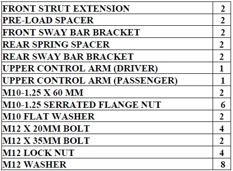
BILL OF MATERIALS
Safety Warning
Before you start installation: ReadyLIFT® Suspension highly recommends that the installation of this product be performed by a professional mechanic with experience working on and installing suspension products. Professional knowledge and skill will typically yield the best installation results. If you need an installer in your area, please contact ReadyLIFT® Suspension customer service to find one of our “Pro-Grade” Dealers.
INSTALLATION BY A PROFESSIONAL IS HIGHLY RECOMMENDED
A Factory Service Manual for your specific Year / Make / Model is highly recommended for reference during installation.
All lifted vehicles may require additional driveline modifications and / or balancing.
A four wheel vehicle alignment will need to be performed after installation of this product.
Speedometer / Computer recalibration is required if changing /- 10% from factory tire diameter.
Use of a Vehicle Hoist will greatly reduce installation time.
Vehicle must be in excellent operating condition. Repair or replace any and all worn or damaged components prior to installation.
Park vehicle on a clean flat surface and block the rear wheels for safety. Engage the parking brake.
Disconnect the vehicle power source at the ground terminal on the battery. Raise the front of the vehicle and support with jack stands at each frame rail behind the lower control arms.
Remove the front wheels and support the lower control arm with a suitable jack.
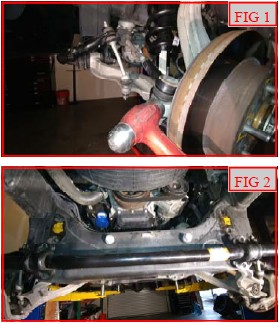
Remove the outer tie rod from the knuckle. Strike the tie rod boss on the knuckle with a dead blow hammer to dislodge the taper. (FIG 1)
Remove the sway bar from the frame. Let hang out of the way. (FIG 2)
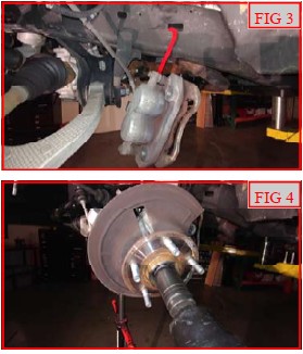
Remove the brake caliper from the knuckle. Using a suitable device, hang the caliper out of the way. DO NOT let the caliper hang by the brake line. (FIG 3)
Remove the brake rotor and set aside.
Remove the axle nut. (FIG 4)
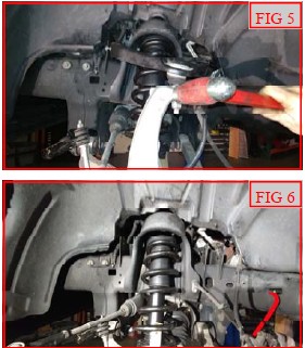
Remove the upper ball joint from the knuckle. Strike the ball joint boss with a dead blow hammer to dislodge the taper. (FIG 5)
Remove the upper control arm from the frame. (FIG 6)
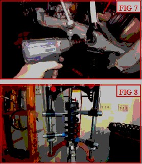
Support the lower control arm with a suitable jack. Remove the lower strut from the lower control arm. (FIG 7)
Loosen the lower control arm at the frame and lower the control arm until the strut clears. The axle will need to be released from the hub bearing to allow enough travel to install the completed strut assembly.
Remove the strut from the frame.
****Caution, the spring is under extreme pressure and can cause bodily injury and/or death if handled improperly.***
Mark the orientation of the strut assembly, spring to strut, and spring to top hat. These will be need to be assembled in the same orientation as factory. Using a spring compressor, relieve spring pressure from the strut top hat. Remove the factory top hat. Remove the plastic spring lock from the top hat. (FIG 8)
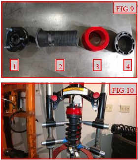
Install the ReadyLIFT® pre-load spacer in between the top hat rubber isolator/dust sleeve and the plastic spring lock. Install the factory top hat onto the strut. See Fig 9 for order: 1. Factory top hat and rubber isolator, 2. Factory dust shield, 3. ReadyLIFT® pre-load spacer, 4. Factory plastic spring lock. Torque to 30-ftlbs. (FIG 9, 10)
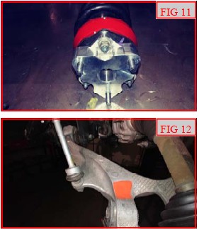
Install the ReadyLIFT® strut extension to the strut assembly using factory hardware. Torque to 25 ft-lbs. (FIG 11)
Mark the area on the lower control arm right above the strut mount. (FIG 12)
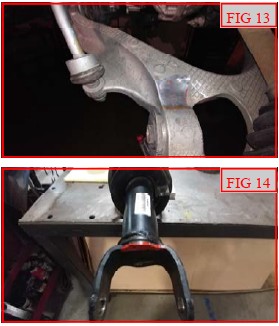
Using a suitable tool, grind down this area for clearance when the strut is installed. (FIG 13)
Mark the bottom of the strut body as shown. This needs to be done to the inside edge of the strut. Note: the strut mounts 180 degrees from the original orientation, so this mark will be on the original outside face which will then be the inside face once installed into the vehicle. (FIG 14)
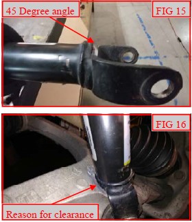
Using a suitable tool, grind down this area at a 45 degree angle for clearance when the strut is installed. Do not grind into the strut body, only on the lower mount. Paint the exposed metal with a quality rust preventative paint. (FIG 15)
Fig 16 shows the reason behind the above clearance steps. This is for full droop clearance and easier install of the lower strut mount. (FIG 16)
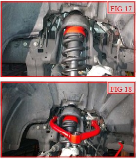
Install the completed strut assembly into the frame using M10 flange nuts. Raise the lower control arm up and install the lower strut mount using factory hardware. Do not tighten at this time. (FIG 17)
Install the bushings and crush sleeves into the ReadyLIFT® control arms using the provided one time grease pack. Lightly grease the bushings and sleeves and slide into the pivot points on the control arms.
Install the appropriate side ReadyLIFT® upper control arm to the frame side that you are working on using factory hardware. (The control arms are identified by the ABS mounting hole, the hole will line up just like the factory arm towards the rear of the vehicle) Do not tighten at this time. (FIG 18)
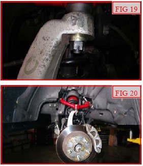
Install the upper ball joint to the knuckle using provided hardware. Make sure to install the ball joint spacer under the nut. Torque to 45 ft-lbs. Install the provided cotter pin. (FIG 19)
Install the rotor and caliper using factory hardware. Torque to 130 ft-lbs. Install the outer tie rod end to the knuckle using factory hardware. Torque to 65 ft-lbs. Install the axle nut. Torque to 185 ft-lbs. (FIG 20)
Install the ReadyLIFT sway bar drops to the frame using factory
hardware. Torque to 45 ft-lbs. Install the sway bar to the
ReadyLIFT drop brackets using M12 x 20mm bolts and washers.
Torque to 45 ft-lbs.
Install the front wheels and lower the vehicle to the ground. Jounce the suspension a few times to get it to settle to the new ride height. Torque the lug nuts to the wheel manufacturer specs, upper strut mount to 30 ft-lbs, upper control arms, lower control arms, and lower strut mount to 120 ft-lbs. Lower control arm to have final torque set by alignment shop. Use an appropriate tool, grease the upper ball joint just until the boot just starts to expand. Do not over grease.
Block the front wheels and jack the rear up. Place jack stands at the frame rails in front of the lower control arms. Removal of the wheels and inner liner is not necessary, but recommended for ease of install.
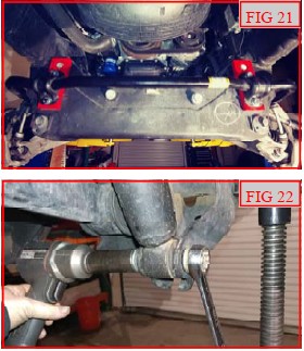
Support the axle with a suitable jack. Remove the lower shock from the axle. (FIG 22)
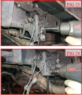
Remove the ABS, brake line bracket and sway bar end link at the frame. (FIG 23, 24)
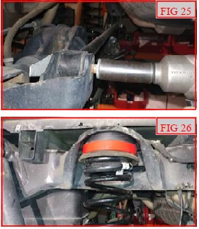
Loosen but do not remove the upper control arms, lower control arms, and track bar hardware at the frame and axle. (FIG 25)
Lower the axle enough to remove the springs. Install the Ready- LIFT® rear spring spacers onto the springs making sure to keep the factory isolator on top of the spring. Raise the axle while locating the spring assembly to the frame. (FIG 26)
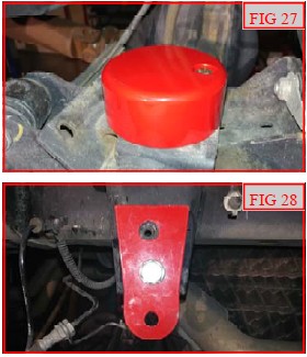
Install the ReadyLIFT bump stop to the axle using M10 X 60MM bolts, washers, and nuts. Torque to 35 ft-lbs. (FIG 27)
Install the lower shock to the axle using factory hardware. Do not tighten at this time.
Install the ReadyLIFT® rear sway bar bracket to the frame using M12 x 35mm bolts, washers, and nuts. (Part shown on outside of frame for reference, install to the inside of the frame.) Torque to 45 ft-lbs. (FIG 28)
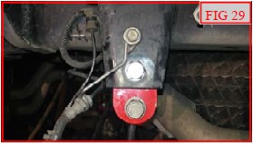
Install the sway bar end links to the ReadyLIFT® drop brackets using factory hardware. Do not tighten at this time. (FIG 29)
Install the brake line brackets to the frame using factory hardware. Torque to 5 ft-lbs.
If removed, install the inner fender liner and wheels. Lower the vehicle to the ground. Jounce the vehicle a few times to get it to settle to the new ride height. Torque the lug nuts to the wheel manufacturer specs, the upper, lower control arms to 200 ft-lbs, track bar hardware to 125 ft-lbs, lower shock hardware to 65 ft-lbs, and sway bar link to 45 ft-lbs. Install the vehicles power source at the negative terminal. Cycle the steering wheel and make sure that there is clearance between all moving components and brake/ABS lines. Adjust as necessary. Have the alignment set to the recommended specs at the back of the instruction manual.
***FAILURE TO PERFORM THE POST INSPECTION CHECKS MAY RESULT IN VEHICLE COMPONENT DAMAGE AND/OR PERSONAL INJURY OR DEATH TO THE DRIVER AND/OR OTHERS***
Final Checks & Adjustments
Once the vehicle is lowered to the ground, check all parts which have rubber or urethane components to ensure proper torque. Torque lug nuts to the wheel manufacturer specs. Move vehicle backwards and forwards a short distance to allow suspension components to adjust. Turn the front wheels completely left then right and verify adequate tire, wheel, brake line, and ABS wire clearance. Test and inspect steering, brake and suspension components for tightness and proper operation. Inspect brakes hoses and ABS lines for adequate slack at full extension, adjust as necessary.
***RECHECK ALL HARDWARE FOR PROPER TORQUE VALUES AFTER 500 MILES, AND THEN PERIODICALLY AT EACH SERVICE INTERVAL THERAFTER.***
Vehicle Handling Warning: Vehicles with larger tires and wheels will handle differently than stock vehicles. Take time to familiarize yourself with the handling of your vehicle.
Wheel Alignment/Headlamp Adjustment: It is necessary to have a proper and professional wheel alignment performed by a certified alignment technician. Align the vehicle to recommended specifications. It is recommended that your vehicle alignment be checked after any off-road driving. In addition to your vehicle alignment, for your safety and others, it is necessary to check and adjust your vehicle headlamps for proper aim and alignment.
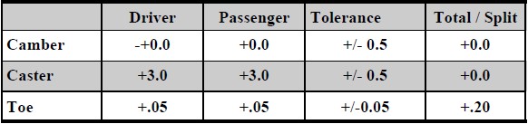
RECOMMENDED ALIGNMENT SPECS