FREE 1 to 3-Day Delivery on Orders $119+ Details
How to Install S & B Cold Air Intake w/ Oiled Cleanable Cotton Filter (15-17 2.7L EcoBoost) on your Ford F-150
Tools Required
- 10mm, 13mm Wrench & Socket
- 5/16” Nut Driver & 1/4” Nut Driver or Flat Blade Screwdriver
- Phillips Screwdriver, Pliers or Channel Locks

Shop Parts in this Guide
- S&B Cold Air Intake with Oiled Cleanable Cotton Filter (15-17 2.7L EcoBoost F-150)
- S&B Cold Air Intake with Oiled Cleanable Cotton Filter (15-17 3.5L EcoBoost F-150, Excluding Raptor)
- S&B Cold Air Intake with Oiled Cleanable Cotton Filter (2017 F-150 Raptor)
- S&B Cold Air Intake with Dry Extendable Filter (15-17 2.7L EcoBoost F-150)
- S&B Cold Air Intake with Dry Extendable Filter (15-17 3.5L EcoBoost F-150, Excluding Raptor)
- S&B Cold Air Intake with Dry Extendable Filter (2017 F-150 Raptor)
BEFORE YOU START
• Please read the entire product guide before proceeding.
• Ensure all components listed on page 6 are present.
• If you are missing any of the components, call our customer support at (909) 947-0015.
• Do not work on your vehicle while engine is hot.
• Make sure the engine is turned off and the vehicle is in Park or the Parking Brake is set.
1. With the ignition switched off and the parking brake set, disconnect the negative battery terminal on the battery. Note: Failure to disconnect the battery may cause the CEL to illuminate upon completion of the installation and subsequent operation. Do not skip this step!
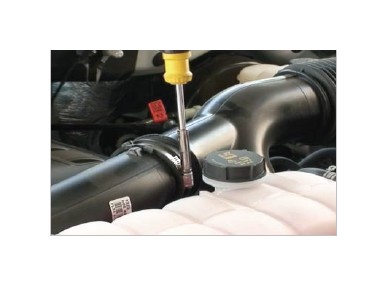
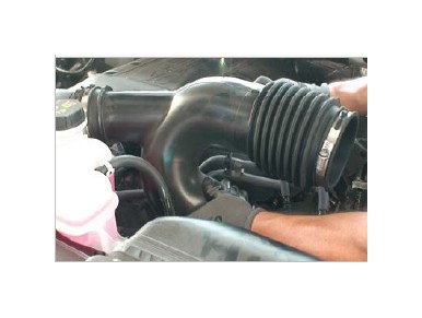
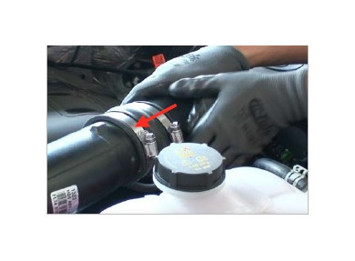
2. Loosen the hose clamp by the stock air box and pull the tube out.
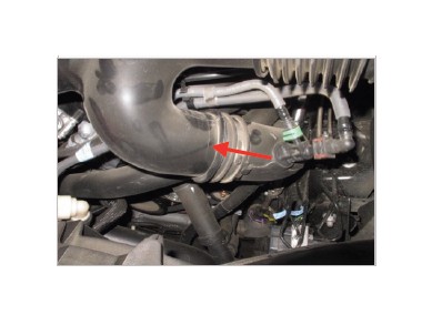
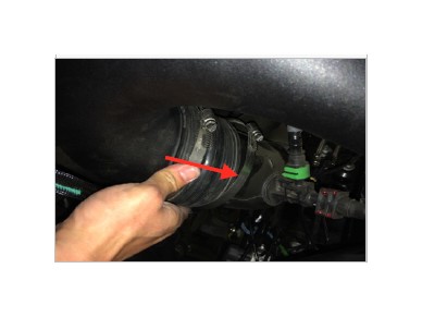
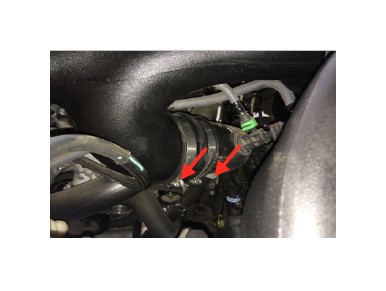
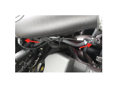
3. Loosen the hose clamp at the tube leading to the turbo inlet on the passenger side.
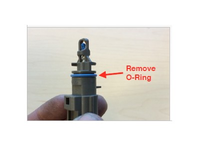
4. Loosen the hose clamp at the tube leading the turbo inlet on the driver side.
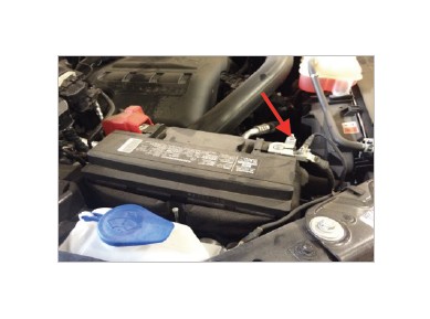
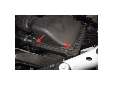
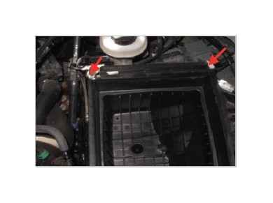
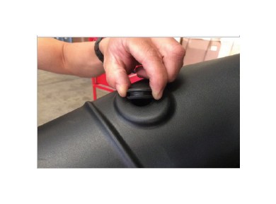
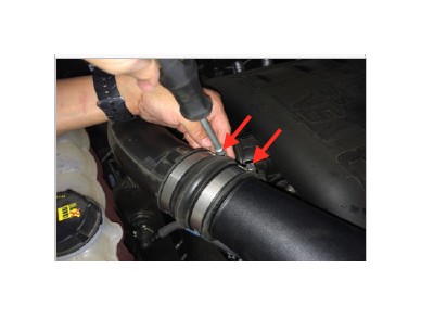
5. Unhook the two latches on the stock air box. For 2017 3.5L Ecoboost Only. Disconnect the clip securing the vacuum line on the stock air box.
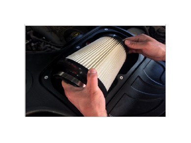
6. Lift and remove both the lid and stock air filter.
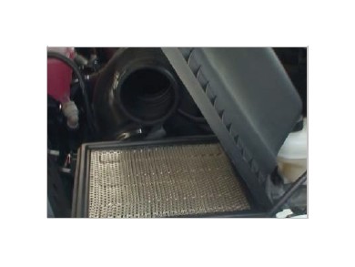
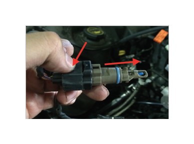
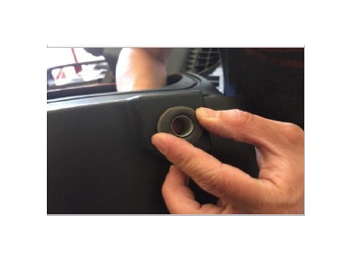
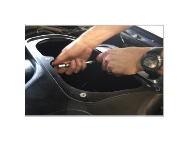
7. Remove the IAT sensor from the stock air tube by turning the sensor counter clockwise and pulling out. You should be able to feel the sensor unlock as you are making the turn. Push down on the wire harness connector tab to remove the wiring harness from the sensor.
8. Lift up and remove the stock air tube.
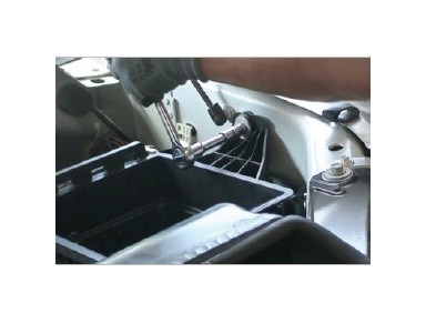
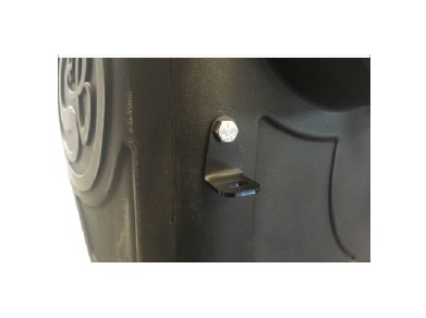
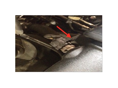
9. Remove the retaining bolt on the stock air box using a 13mm socket. Note: The retaining bolt will be reused in Step 22.
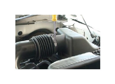
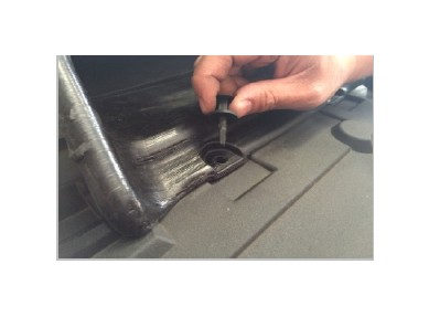
10. Remove the plastic rivets on the stock air inlet using a flat head screwdriver.
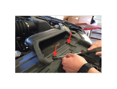
11. Disconnect the two wire harness clips on the stock air box.
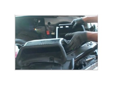
12. Lift and remove the stock air box.
13. Remove the grommet and metal bushing from the stock air box. Removing the metal bushing first will make removing the grommet easier.
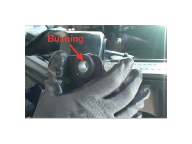
14. Install the grommet into Air Box (A) first and then install the metal bushing from the inside.
15. For 2017 3.5L Ecoboost Only. Install the Vacuum Line Bracket (W) with the 1/4-20 Screw (X), Washer (Y) and Locknut (Z).
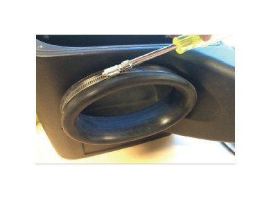
16. Install the Cuff (C) and #104 Hose Clamp (L) onto the side of the Air Box (A). Make sure that the rubber pull tab on the tube seal is on the bottom. Tighten the hose clamp.
17. Install the Front Inlet (G). Use the supplied Plastic Rivet (H) to secure the front inlet to the Air Box (A). Use two plastic rivets on each hole and pinch them together to lock them in place.
18. Install the Grommet (V) into the Intake Tube (B).
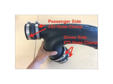
19. Install the Hump Coupler (P) with Hose Clamp #52 (R) into the Intake Tube (B) that leads to the passenger side. Do not tighten the hose clamps. Install the Straight Coupler (U) and Hose Clamp #72 (T) that leads to the driver side. Do not tighten the hose clamps. To make the installation onto the turbo inlet tubes easier, try to slide the coupler in over the air intake tube as much as possible.
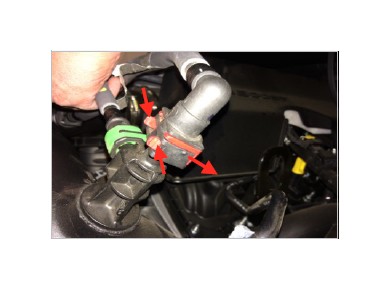
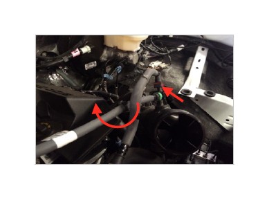
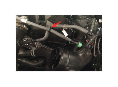
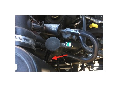
20. For 2.7L EcoBoost Only. You will need to reroute the vent hose. Remove the vent hose connector by pinching the red clip and pushing in through the connector. Reroute the vent hose as shown. Reorient the black plastic hose clip and snap in place the two vent hoses. Then reinstall the red connector.
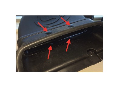
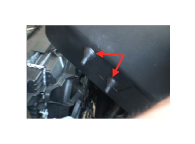
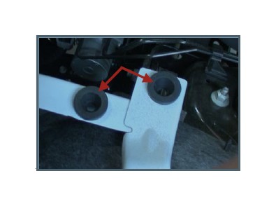
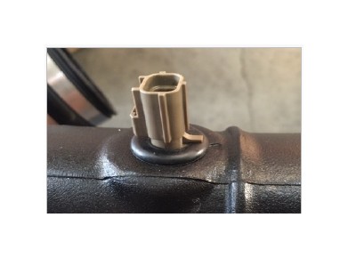
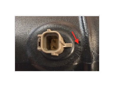
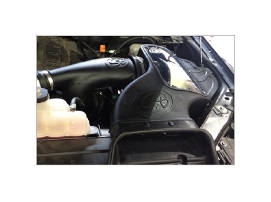
21. Install the Air Box (A). Make sure that the box prongs are aligned with the factory grommets. Push down on the air box to make sure that the prongs are completely seated.
22. Reinstall the retaining bolt removed in Step 9 and tighten the bolt to secure the Air Box (A). Install the retaining bolt from inside the air box.
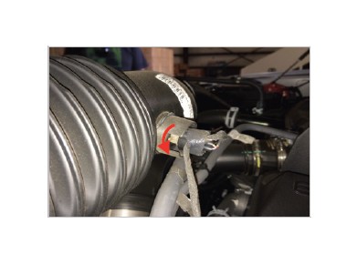
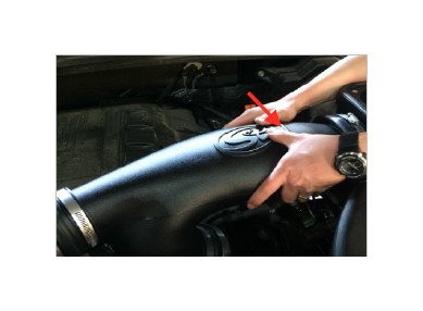
23. Install the IAT Sensor into the Intake Tube (B). Make sure to remove the IAT Sensor O-Ring prior to installing. Use a twisting motion to make it easier to guide the sensor into the grommet. Make sure that the sensor is seated all the way so that the sensor tab is touching the grommet and is lined up with the triangle mark located on the air intake tube.
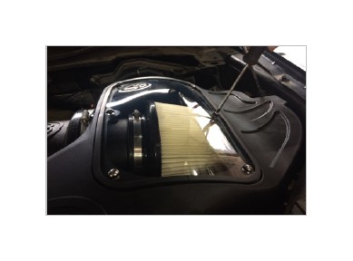
24. Place the Air Filter (D) inside the Air Box (A). Turn the filter sideways and slide it into the box. Do not tighten the hose clamp.
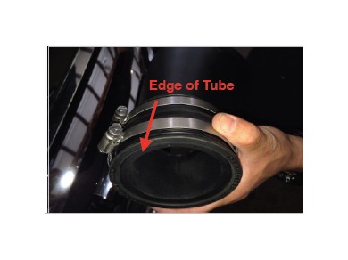
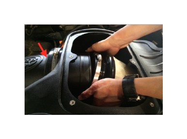
25. Feed the Intake Tube (B) through the Cuff (C) and into the air box until the air filter fits up to the bead. As you are feeding, try to align the air intake tube with the turbo inlet tubes..
26. Once the bead is up to the Cuff (C). Slide the Air Filter (D) onto the Intake Tube (B).
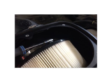
27. Tighten the Hose Clamp #88 (K) at the Air Filter (D).
28. Slide the Straight Coupler (U) over the driver side turbo inlet tube on the bottom. Leave the hose clamps loose for now.
29. Slide the Hump Coupler (P) over the passenger side turbo inlet tube.
30. Tighten both #52 Hose Clamps (R).
31. Tighten both #72 Hose Clamps (T) on the driver side.
32a. For 2015-2016 Models and 2017 2.7L EcoBoost Only. Reconnect the wiring harness back into the IAT sensor.
32b. For 2017 3.5L EcoBoost Only. Connect one end of the IAT Sensor Extension Harness (AA) into the stock IAT harness and the other end into the IAT sensor. Use zip ties to secure the extension harness from any hot surfaces and moving components that may cause damage.
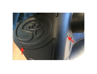
33a. For 2015-2016 Models and 2017 2.7L EcoBoost Only. Insert the two wire harness clips disconnected in Step 11 into the holes on the side of the Air Box (A). For 2017 3.5L EcoBoost Only. Insert one wire harness clip into the hole under the S&B Logo and use zip ties secure the other wire harness clip away from any hot surfaces and moving components that may cause damage.
33b. For 2017 3.5L EcoBoost Only. Reconnect the clip securing the vacuum line into the slot on the Vacuum Line Bracket (W).
34. Use the two provided Plastic Rivet (J) to secure the Front Inlet (G) onto the radiator cover. Firmly push down on the center pin of the plastic rivet until it locks into the closed position.
35. Remove the protective covering from the Clear Lid (E).
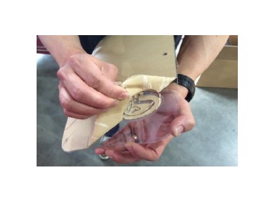
36. Install the Lid Seal (F) around the Clear Lid (E).
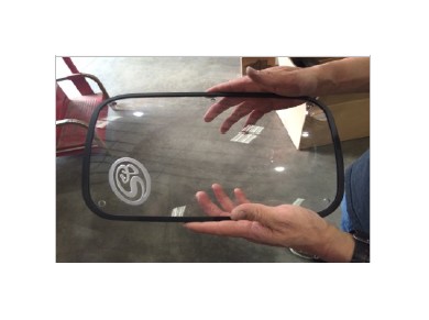
37. Place the lid on top of the Air Box (A) and secure the lid using the six provided 10-24 Screw (N) and Sealing Washer (M). Do not over tighten.
38. Reconnect the negative terminal on the battery. Inspect your installation, make sure the kit is properly positioned and all fasteners are secure. Keep all stock parts incase you would ever need to reinstall the stock intake. The installation is now complete.
Performance Testing
• Engage parking brake and start your engine. Listen for abnormal noises. If an air leak is detected, re-inspect hoses and connections as they may need to be repositioned and tightened.
• S&B FILTERS recommends that you keep your OE intake system in the event it is required in the future.
• In order to maintain your warranty, all connections and components must be checked periodically for alignment and for proper tension on all connections. Failure to do so may void your warranty.
• Use only S&B FILTERS cleaning and oil products to service your filter. Using any other brand oil and or cleaners on your S&B air filter may void your warranty.
Warning!
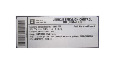
If your vehicle has a Vehicle Emission Control Information decal affixed to the factory airbox, a new replacement label must be obtained and installed in a readily visible position in the engine compartment in order to remain CARB compliant. Failure to do so will prevent the vehicle from passing a smog check. Replacement labels can be ordered from your local dealership. Regulations state that the VECI label shall not be affixed to any equipment which is easily detached from the vehicle. Label placement, under the hood on a painted surface is recommended.
Emissions Standard
The California Air Resource Board (CARB) requires that an E.O. identification label be applied to the vehicle in order to pass a smog check inspection when a Performance Intake Kit has been installed. You must place the E.O. label provided on or near the intake kit after installation so that a smog check technician can easily verify the E.O. number. As of April 2009, S&B has never had a product where CARB denied an exemption request; however, the exemption process with CARB can take as long as 18 months. Check the status of the exemption process by looking up a specific part number at www.sbfilters.com. The CARB Exemption number and/or status is listed under the Product Details section for each part number. If the status shows as “Pending,” CARB has yet to issue an exemption. Products that have not been issued an EO number are street legal in most states, but may not be used on emission controlled vehicles in the state of California and are for off road use only. If you purchased your kit from S&B Filters directly, we will automatically mail you your Exemption Sticker when it is issued to us. If you purchased your kit from an authorized S&B Filters Dealer, log onto our web site and register to receive your Exemption Sticker.
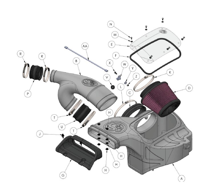
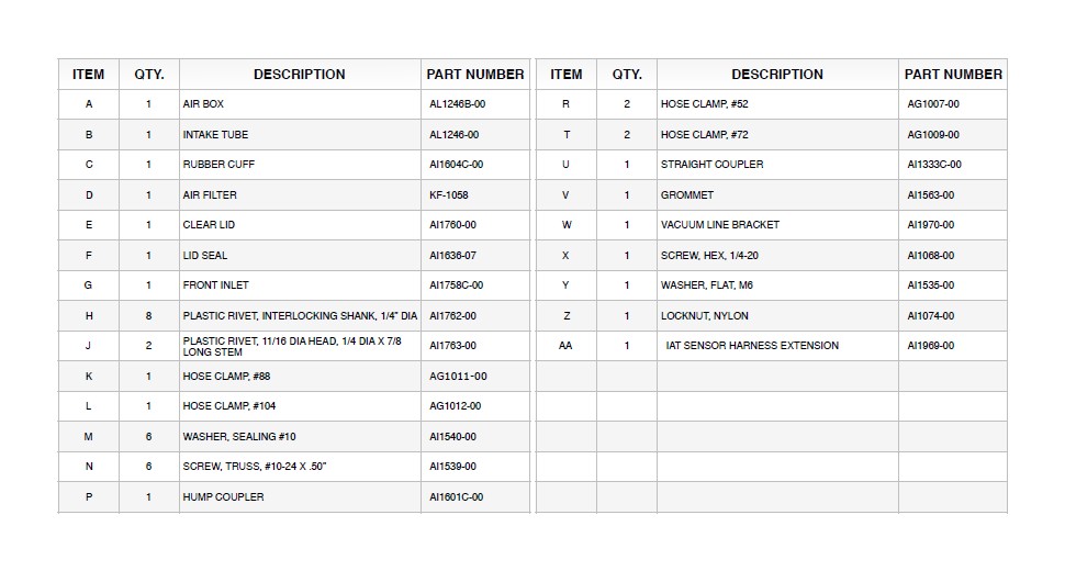
EXPLODED VIEW